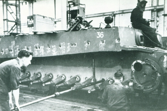
Torsion bars being inserted through the hull during Tiger assembly.
Note the swingarms waiting to receive the roadwheels.
The Tiger I's suspension system consisted of interleaved roadwheels mounted on axles attached to torsion bars, along with a drive sprocket and idler wheel over which traveled the track.
The Tiger had a total of 16 torsion bars, with 8 bars running transversely through the hull on each side of the tank, being anchored in a socket type housing on the opposite side. The torsion bars were 5 feet 4.75 inches long (1644.6mm) and either 55 or 58mm in diameter with splined ends. On the outer end of each torsion bar was a swing arm and on the end of each swing arm was the axle. To save space, the swing arms were angled forward on the driver's side and backward on the opposite side.

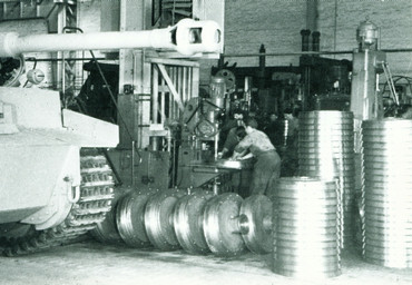
Early Tigers had dished steel wheels with rubber tires. The rubber tire design was adapted from an early development vehicle since the Tiger was rushed into production and could not be delayed. The rubber was vulcanized to the wheels and also had internal wire support but the use of rubber still caused many durability problems. There were 3 wheels per axle, for a total of 24 per side, and the wheels of one axle overlapped the wheels of the next. Each wheel was 31.5 inches (80cm) in diameter.
 |
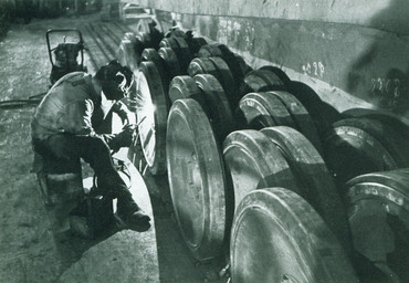 |
| Fascinating picture of unfinished roadwheels stacked for assembly. | A Henschel worker performs welding work on the roadwheels. |
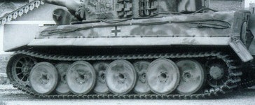
To reduce costs and make production easier, new steel wheels were introduced in January 1944. Because these steel wheels could handle heavier loads than the earlier rubber-tired versions, the outer row of wheels was left off, resulting in 2 wheels per axle or 16 per side.
 |
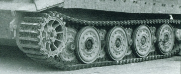 |
| First style rubber-rimmed roadwheels. | Second style steel roadwheels. |
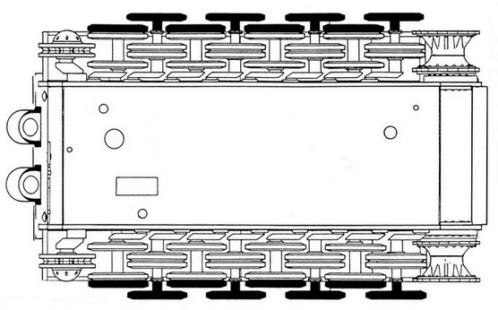
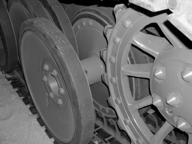
The drive sprocket was cast from manganese steel and was 36 inches (91.44cm) in diameter. It had 10 spokes and 20 teeth. The sprockets drive teeth were on twin removable rings bolted to the sprocket wheel. The rear idler wheel was 27 inches (70cm) in diameter. It was cranked using draw bolts to adjust track tension. This was done by removing covers on the rear tail plate to access the adjustment bolt. The covers locked the adjustment in place when they were put back on.
 |
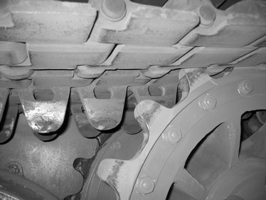 |
| View of the drive sprocket as it passes between the front road wheels. | Closeup showing the drive sprocket teeth as they engage the track. |
The Tiger had two different sets of tracks, combat tracks and transport tracks. The combat tracks were much wider than the transport tracks and they were what the Tiger normally used since their larger footprint reduced ground pressure considerably. But because they extended well past the hull, combat tracks made the Tiger too wide to transport easily. Thus for transport, the combat tracks were replaced with transport tracks. These allowed the Tiger to fit on railcars. When the transport tracks were fitted to early and mid production Tigers, the outermost row of roadwheels on each side was removed. Steel-wheeled Tigers did not have the outermost row.
| Combat track | Transport track | |
| Width | 2 ft 4.5 in (72.5cm) |
1 ft 8.5 in (52.1cm) |
| Weight of 1 link with pin |
66.375 lbs (30.11kg) |
46.5 lbs (21.09kg) |
| Track pressure | 14.8 lbs/sq. in. (1.04kg/sq.cm.) |
20.4 lbs/sq. in. (1.43kg/sq.cm.) |
The first 20 Tigers produced had left and right hand track links. In October 1942 this was changed so that the links were identical on each side. The left hand track was simply turned around and mounted backwards. In icy conditions ice cleats could be bolted onto these track links. The combat track castings were revised in October 1943 when chevrons were added to the link surface for additional traction.There were 96 track links per track, connected by 1.1 inch (2.8cm) diameter track pins. There were several different methods used to secure the track pins ranging from C clips to locking rings held in by dowel pins.
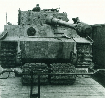
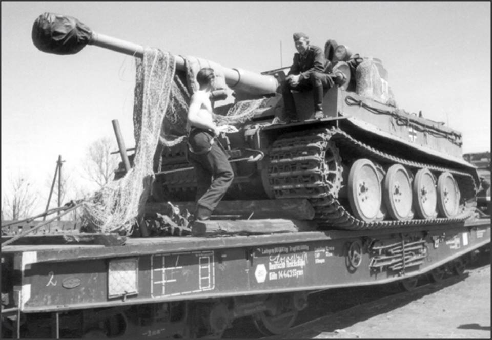
A good view of the wider combat tracks overhanging the side of the railcar.
The Tiger I had hydraulic piston type shock absorbers on the front and rear axles only. These were mounted inside the hull which protected them from damage. There were also 2 bump stops on each side of the hull that prevented overtravel of the swingarms on the 1st and 8th torsion bars. Lastly there were deflector plates mounted on the hull just in front of the rear idler wheels. These were used to push any track pins that were working loose back into place.
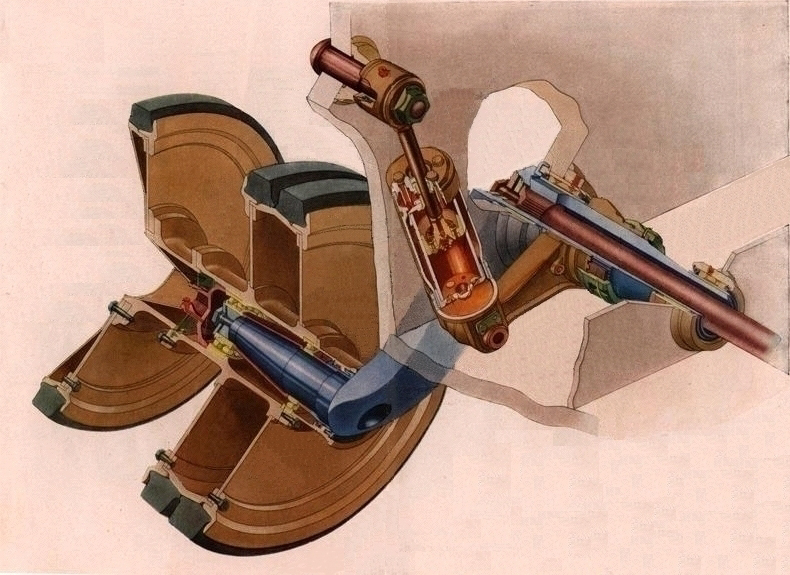
All in all the Tigers suspension system was smooth and steady even over rough
terrain. The biggest flaw to this system was the vulnerability of the roadwheels
to being frozen in place. In winter conditions such as those on the Eastern
Front, ice and mud could become packed and frozen between the roadwheels
rendering the vehicle immovable. This often resulted in broken tracks. However a
benefit of the multiple rows of overlapping wheels was the protection they gave.
Most shells striking the suspension exploded before reaching the hull. And for
such a large, heavy tank, the system generally provided a remarkably comfortable
ride for the crew. In the end, the hastily designed suspension kept the Tigers
rolling right up until the end of the war.